First class Repair and Maintenance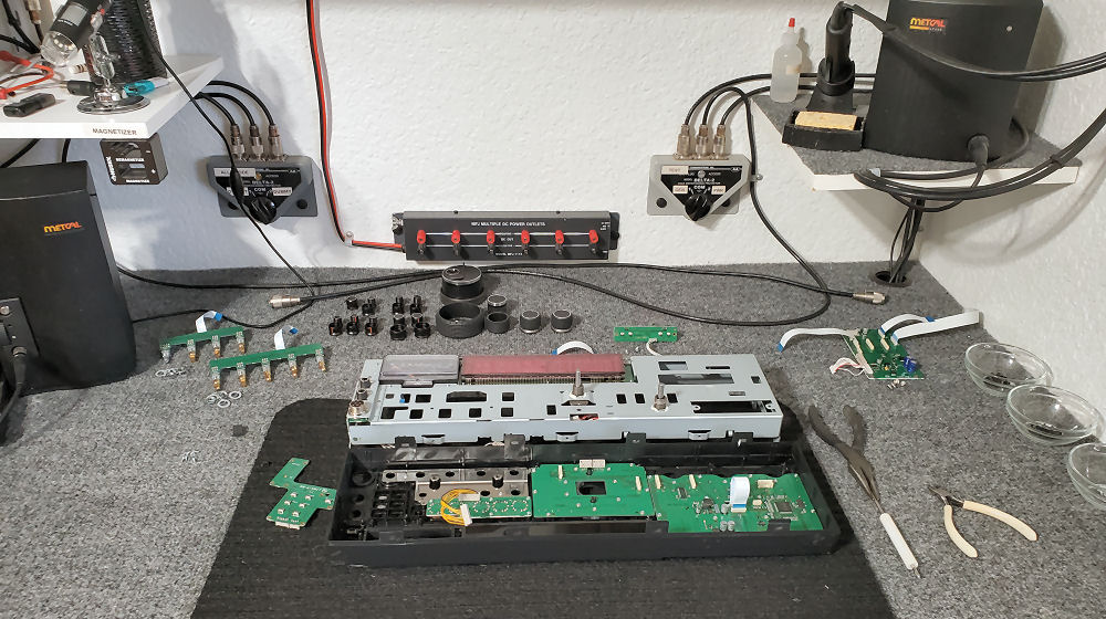 FTDX5000
in for OLED replacement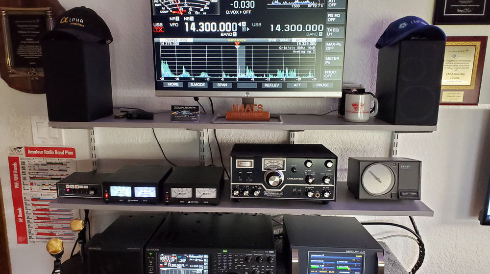 Shack #1
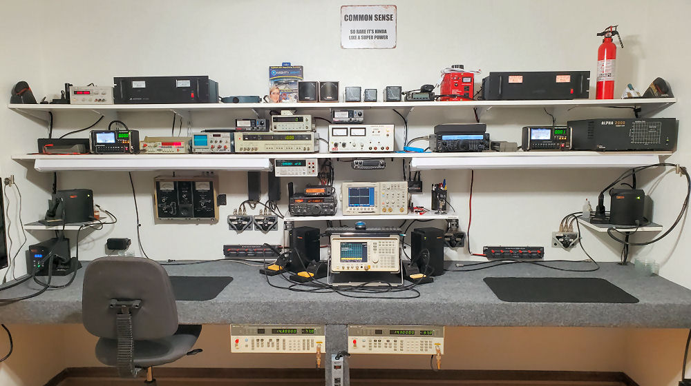
in the Shop for Monitoring HF while working on radios and amplifiers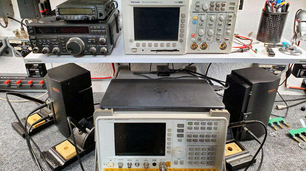
Spectrum Analyzer, DSO and test radios. 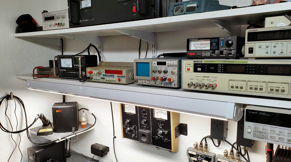
LCR, DMM and assorted equipment for repairs. 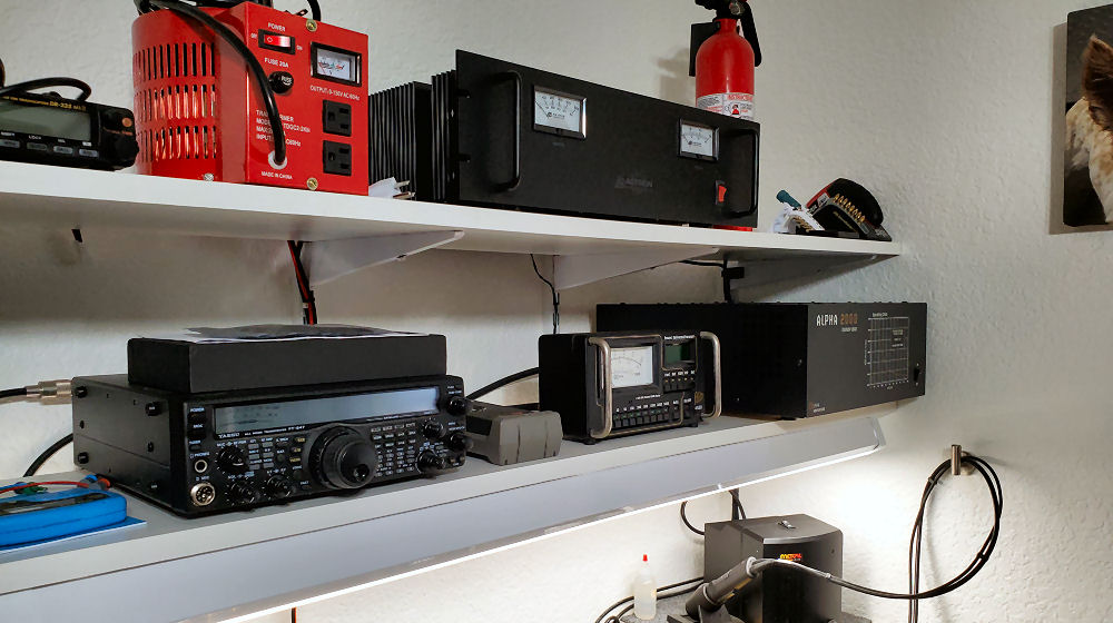
Dummy Loads, Power Supplies and more test radios. 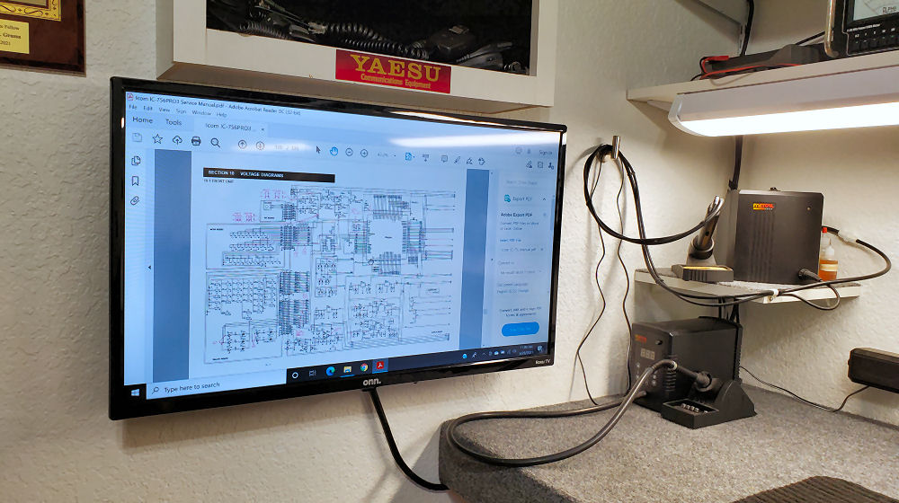
Widescreen next to the bench for Service Manual Viewing 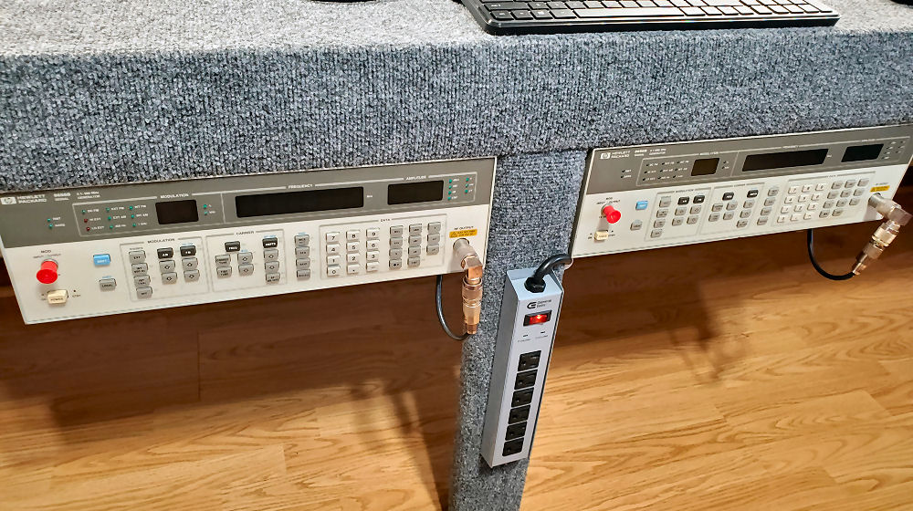
Dual Generators for a complete redundant set-up so I can fix two at a time if needed...
I Build Mercury Amplifiers, km3km
Service Center for ACOM Amplifiers, ACOM
Accepting all types of Amateur Radios and Amplifiers needing Repair!
Kenwood , Ten Tec, Yaesu, Icom , Ameritron, Alpha, THP, Mirage, and just about all other brands. If you have any questions or comments, I would love to hear from you!
73 Bill N4ATS